01 Introduction
Due to their excellent static fatigue and creep resistance, nickel-based superalloys account for more than 40% of the superalloys used in advanced aircraft engines. Alloys produced by Selective Laser Melting (SLM) exhibit unique microstructures and enhanced mechanical properties, making SLM highly suitable for manufacturing nickel-based superalloy components in aero-engines. However, the high alloy content of nickel-based superalloys results in low thermal conductivity, a wide solidification temperature range, a high thermal expansion coefficient, and severe solidification shrinkage. These characteristics easily lead to coarse grains, segregation, and micro-cracks in the structure. Nickel-based superalloys fabricated by SLM are prone to solidification cracking (SC), liquation cracking (LC), ductility-dip cracking (DDC), and strain-age cracking (SAC), all of which reduce mechanical performance and shorten service life. Despite progress in crack-suppression strategies—such as alloy powder composition design, nucleant addition, optimized scanning strategies, and post-heat treatment—cracking remains a major issue affecting SLMed nickel-based superalloys.
02 Types of Cracks
During solidification, there are two temperature intervals where significant plasticity reduction occurs, and both are closely related to crack initiation. The first interval lies between the solidus temperature (TS) and liquidus temperature (TL), which represents a high-risk region for hot cracking (the brittle temperature range). During the thermal cycles of Selective Laser Melting (SLM), elemental segregation commonly occurs in interdendritic regions (IRs). This segregation lowers the solidus temperature in the interdendritic regions and causes non-equilibrium solidification. When dendrite arms coalesce, insufficient liquid feeding traps solute-rich molten metal within interdendritic regions, forming low-strength semi-solid zones. These zones are susceptible to thermal stresses, resulting in voids, cracks, and porosity. Similar to solidification cracking (SC), liquation cracking (LC) also forms at early stages, driven by the rupture of liquid films along grain boundaries. Liquation cracking involves elemental segregation, which lowers the solidus temperature of the interdendritic regions (IR) and forms low-melting-point phases through eutectic reactions. During the SLM thermal cycles, these low-melting-point phases repeatedly melt and maintain metastable liquid films at the interfaces between precipitates and the matrix. These films fracture under thermal stress, triggering crack formation.
Ductility-Dip Cracking (DDC):
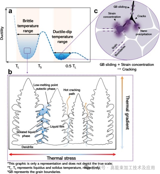
When the temperature is below the dynamic recrystallization threshold but within the grain-boundary sliding regime (approximately 0.5–0.7 of the solidus temperature), grain-boundary sliding may induce DDC.
Strain-Age Cracking (SAC):
γ′ precipitates and carbides hinder dislocation motion, causing stress concentration that exceeds stress relaxation capacity, thereby driving SAC formation. SAC and DDC can synergistically interact and influence crack propagation.
Cold Cracking:
Cold cracking may occur after solidification and is typically induced by inconsistent cooling rates that lead to uneven shrinkage. Cold cracks are relatively rare in SLM-fabricated nickel-based superalloys but can be mitigated through post-heat treatment.
![]()
Figure 1. Crack formation mechanism. (a) Plasticity versus temperature curve; (b) Schematic diagram of hot crack; (c) After solidification, as the temperature decreases, grain boundary slip (GBS) is activated in a creep-like manner, triggering grain boundary shear (DDC). Rapid precipitation of the γ′ phase hinders GBS, leading to strain localization and the formation of SAC cracks [1].
![]()
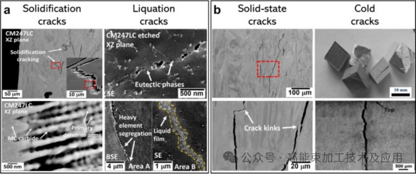
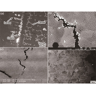
Figure 2. Morphology of hot crack, solid crack, and cold crack. (a) Morphology of hot crack [2]; (b) Morphology of solid crack [3].
03 Crack Formation Mechanisms
During SLM, dendrite morphology is primarily governed by the thermal gradient (G) and the solidification front growth rate (V). The product G·V represents the cooling rate and determines dendrite size—the higher the value, the finer the structure—with G having a stronger influence than V. The G/V ratio determines dendrite morphology, and lower ratios favor the formation of equiaxed dendrites. At the top of the melt pool or within overlap zones, high thermal gradients promote fine equiaxed dendrites, which enhance crack resistance via uniform load distribution.
The [001]-oriented γ′ dendrites possess lower elastic modulus than [110] or [111] orientations. When aligned with the maximum thermal gradient vector—from the top to the bottom center of the melt pool—they preferentially grow, forming columnar grains with {001}⊥BD cubic texture that span multiple deposited layers. These columnar grains contain elongated dendrites aligned with the maximum thermal gradient. Such uneven load distribution results in anisotropic crack resistance. Outside the central region, gradient vectors with larger X-components dominate, promoting competitive growth between [010]- and [001]-oriented grains. In overlap zone 2, repeated layer remelting causes these gradient vectors to compete, resulting in columnar grains with varied orientations and forming dissipated dendrite morphology. Misalignment between dissipated dendrites leads to load-vector mismatch, promoting crack initiation and severely weakening the crack resistance of columnar grains.
The γ′ phase strengthens the alloy by impeding dislocation motion. Its Burgers vector is twice that of the γ matrix, making dislocation nucleation, accumulation, and movement difficult within the γ matrix. When dislocations move from the γ matrix into the γ′ phase, they must overcome a significant energy barrier; otherwise, they become trapped at the γ/γ′ interfacial “network,” which relieves mismatch strain between the two. Although the γ matrix can accommodate some dislocations, excessive dislocation accumulation may trigger cracking at the γ/γ′ interface (intergranular SAC). Meanwhile, elemental diffusion leads to γ′ coarsening, increased volume fraction, and more cubic morphology, all of which promote cracking. Elemental partitioning into the γ′ phase changes its structure and increases lattice mismatch between γ and γ′, making γ′ more cubic. Nickel-site substitution increases mismatch, while aluminum-site substitution reduces it. Excessive mismatch triggers γ′ rafting, where precipitates align like “rafts.” Rafting causes dislocations to pile up at raft edges, accelerating alloy degradation. The stress generated by rafting also induces grain-boundary sliding within the γ matrix, further promoting grain-boundary cracks (grain-boundary decohesion, DBC).
![]()
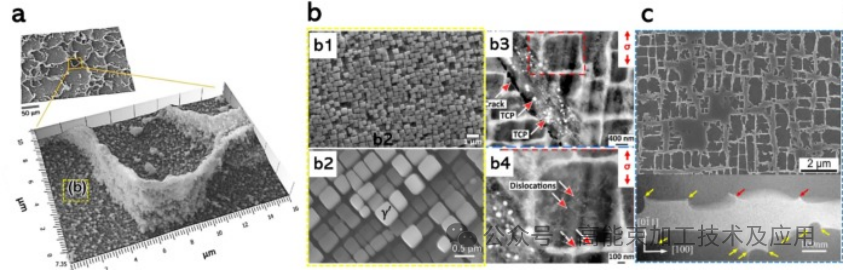
Figure 3. (a) Electron micrograph of the γ′ phase after post-heat treatment; (b1–b2) magnified view of (a) and (b3–b4) dislocation distribution around the γ′ phase; (c) micro protrusions at the interface observed along the [010] axis and magnified view of them.
04 Summary
SLM technology significantly enhances the mechanical performance of nickel-based superalloys, but the low thermal conductivity, wide solidification temperature range, high thermal expansion coefficient, and severe solidification shrinkage associated with high alloy content increase the risk of crack formation. Crack types include solidification cracking, liquation cracking, ductility-dip cracking (DDC), and strain-age cracking (SAC), all of which degrade mechanical performance and shorten service life. Although strategies such as alloy powder design, scanning-strategy optimization, and post-heat treatment can suppress crack formation, cracking remains one of the main challenges in SLM-processed nickel-based superalloys. Future research should focus on optimizing SLM process parameters, developing new alloy powders, and exploring more effective post-processing methods to reduce crack formation and improve the reliability and service life of SLM-manufactured nickel-based superalloy components.
References:
[1] Z. Quan, Q. Jia, Z. Zhang, Y. Wang, L. Ma, Q. Hu, F. Guo, Composition design for laser powder bed fusion (LPBF) fabricated Ni-based superalloys: A review, Journal of Manufacturing Processes, 155 (2025) 119-136.
[2] B. Guo, Z. Yang, Q. Wu, C. Xu, D. Cui, Y. Jia, L. Wang, J. Li, Z. Wang, X. Lin, J. Wang, F. He, Multi-scale annealing twins generate superior ductility in an additively manufactured high-strength medium entropy alloy, International Journal of Plasticity, 179 (2024) 104045.
[3] X. Zhang, H. Chen, L. Xu, J. Xu, X. Ren, X. Chen, Cracking mechanism and susceptibility of laser melting deposited Inconel 738 superalloy, Materials & Design, 183 (2019) 108105.
[4] C. Booth-Morrison, R.D. Noebe, D.N. Seidman, Effects of tantalum on the temporal evolution of a model Ni–Al–Cr superalloy during phase decomposition, Acta Materialia, 57 (2009) 909-920.
[5] M. Ooshima, K. Tanaka, N.L. Okamoto, K. Kishida, H. Inui, Effects of quaternary alloying elements on the γ′ solvus temperature of Co–Al–W based alloys with fcc/L12 two-phase microstructures, Journal of Alloys and Compounds, 508 (2010) 71-78。
**--Cite the article published by 高能束加工技术 on December 10, 2025, in the WeChat public account "High-Energy Beam Processing Technology and Applications."