01 Overview
Due to their high energy density, low self-discharge rate, and long cycle life, lithium-ion batteries have become the most critical power source for electric vehicles (EVs). The primary battery formats used in EVs are cylindrical and prismatic cells. Power battery systems are typically designed and manufactured based on a cell–module–pack architecture, where the individual cells are commonly interconnected via busbars. These systems must operate reliably under harsh driving conditions, such as vibrations, high temperatures, and potential collisions. Therefore, how to safely and efficiently weld hundreds or even thousands of joints in battery modules is crucial to the overall reliability and safety of the battery system.
Laser welding is widely regarded as the most promising joining technology due to its advantages, including concentrated heat input, high welding speed, minimal heat-affected zones, low deformation, and excellent compatibility with automation and system integration. As such, it is increasingly adopted in the manufacturing of power battery systems.
![]()
Figure 1 Commonly used module structures of battery packs (square-shell batteries and cylindrical batteries)
![]()
Figure 2 Schematic diagram of battery and busbar connection
Battery-to-Busbar Welding
Welding between battery electrodes and busbars is one of the most critical processes in battery pack manufacturing. The quality of these welds directly affects the reliability of the battery pack and imposes stringent requirements. Inadequate weld strength increases internal resistance and impairs the battery's power delivery. Excessive heat input can penetrate the electrode cap of the cell, leading to electrolyte leakage or internal short circuits. Battery housings are usually made of aluminum or steel, while busbars are typically aluminum or copper, resulting in combinations such as aluminum-to-copper, aluminum-to-steel, or copper-to-steel—all of which pose unique challenges.
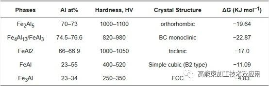
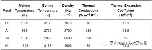
Aluminum-to-steel joints are particularly difficult due to large differences in their melting points, thermal conductivity, and thermal expansion coefficients. Moreover, Fe and Al have low mutual solubility, and their fusion often results in brittle intermetallic compounds (IMCs), which are metallurgically incompatible. IMC formation, such as Fe₂Al₅, Fe₄Al₁₃, FeAl₂ (Al-rich phases), and FeAl, Fe₃Al (Fe-rich phases), can cause weld defects like microcracks and porosity. Al-rich IMCs are harder and more brittle, making cracks more likely, while Fe-rich IMCs offer better toughness and ductility. Thermodynamically, Al-rich phases tend to form more easily due to lower Gibbs free energy, with Fe₂Al₅ being the most stable.
Excessive IMC formation increases electrical resistance and joule heating during charge/discharge cycles, reducing battery lifespan. Therefore, controlling IMC content in the weld zone is critical.
![]()
Figure 3 Common intermetallic compounds in aluminum-steel welding
Process Optimization Studies:
Yang et al. found that shallow weld penetration favors Fe-rich IMC formation, improving joint strength. Deeper penetration results in Al-rich IMCs, degrading mechanical properties.Chen et al. introduced a magnetic field during welding of 301 stainless steel and 5754 aluminum. It inhibited carbon diffusion, refined austenite grains, reduced Al content at the interface, and minimized IMC-related cracking.
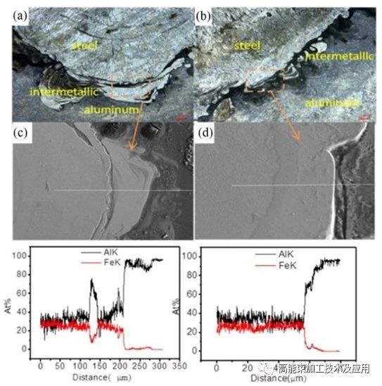
![]()
Figure 4 Analysis of the interface layer of aluminum/steel weld
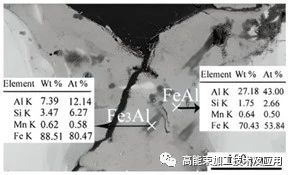
Torkamany et al. welded 0.8 mm low-carbon steel (St14) to 2 mm 5754 aluminum. Excessive laser power and pulse duration increased Al content and IMCs, leading to hot cracking. Optimal parameters (1430 W, 5 ms pulse, 4 mm/s) yielded defect-free joints with minimal IMCs.
![]()
Figure 5 SEM image of the crack around the aluminum/steel weld
Filler Wire and Interlayer Strategies:
Zhang et al. used Al–5Si interlayers to join H220YD steel and AA6016, forming Al₈Fe₂Si and other phases. Thicknesses beyond 10 µm reduced strength.
Xia et al. found that Si interlayers helped reduce required laser power and improved joint toughness during 6061-T6 to DP590 welding.
![]()
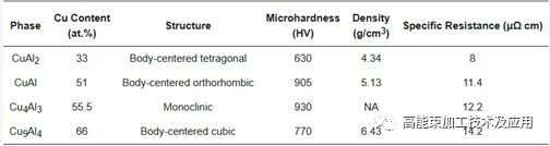
Figure 6 Common intermetallic compounds in aluminum/copper welding
Copper-to-Aluminum Welding
During Cu–Al laser welding, various IMCs such as Cu₂Al, Cu₄Al₃, CuAl, and Cu₉Al₄ can form, significantly impacting weld microstructure and mechanical properties. The high energy density and rapid cooling in laser welding reduce IMC formation. Additionally, the use of filler materials like Ag, Ni, or Sn can mitigate the formation of brittle phases.
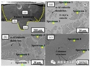
![]()
Figure 7 SEM image of the weld area of aluminum/copper welding
Lee et al. studied pure Al and Cu welds. With Al on top, Cu distributed uniformly. When Cu was the top material, heavier Cu mixed downward into Al. Higher welding speeds (up to 50 m/min) suppressed IMC formation and improved tensile strength (up to 205 MPa for bottom Al).
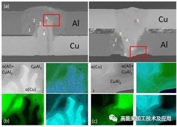
![]()
Figure 8 EDS image of aluminum/copper lap joint
Mai et al. achieved crack-free welds by offsetting the laser 0.2 mm toward the aluminum side.
Weigl et al. used AlSi12 filler for both Cu and Al, finding that higher Si content enhanced ductility via CuSi₃ and AlSi12 IMCs.
![]()
Figure 9 Common intermetallic compounds in copper/steel welding
Copper-to-Steel Welding
Welding copper to steel is also challenging due to stark differences in melting points and thermal conductivities. In the Fe–Cu phase diagram, high-temperature immiscibility causes liquid phase separation, forming droplets that compromise weld continuity. Cu diffusion into steel grain boundaries can lead to hot cracking.
Mannucci et al. welded 316L stainless steel to Cu. The weld pool was asymmetric, with a "keyhole" structure due to Marangoni convection. Shifting the laser toward the Cu side yielded better welds.
![]()
Figure 10 Copper/steel welding butt joint
Li et al. observed liquation cracking and porosity in stainless steel–Cu welds. Cracks formed via Cu diffusion, IMC accumulation at grain boundaries, and thermal stress. At 125 kJ/m, cracks reduced due to molten Cu's self-healing. Porosity was linked to keyhole instability, not cracking. Refocusing the beam onto the steel side enhanced flow and reduced defects.
![]()
Figure 11 Formation mechanism of liquefaction cracks in copper/steel welding
03 Battery Housing Welding
Sealing the battery enclosure—especially for hard casings—requires high-quality welds with low heat input due to the thin-walled structures. Housings are typically made of aluminum or stainless steel. Aluminum alloys are preferred for their lightweight, strength, corrosion resistance, and formability, but welding aluminum poses challenges due to high thermal conductivity and expansion, often resulting in cracks and porosity.
Aluminum oxide layers (Al₂O₃) and surface contaminants increase porosity risks at high temperatures. Hydrogen and other gases dissolve easily in the molten pool, but rapid solidification traps them, forming voids.
Innovative Welding Techniques:
Wu et al. proposed using a fiber laser with focused rotary and vertical oscillation to weld 1060 aluminum. Vertical oscillation determined weld depth, while rotational amplitude affected appearance. A 0.45 mm rotation radius reduced porosity by 91% compared to static beams.
![]()
Figure 12 Cross-section of aluminum alloy welding weld
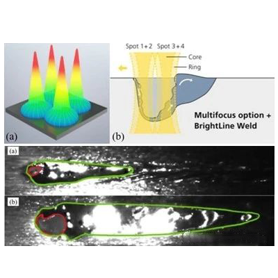
Mauritz et al. applied beam shaping to split a single laser spot into four equal beams. This "multi-spot" method enlarged the keyhole area by 10.6×, enhanced melt pool stability, halved pore size variation, and doubled weld length. X-ray inspection showed significantly reduced porosity and improved weld quality.
![]()
Figure 13 Laser spot shaping and welding process diagram
04 Conclusion
Laser welding offers a high-energy-density, non-contact method with precise heat control, making it ideal for joining dissimilar materials in EV battery systems. Significant progress has been made in dissimilar metal welding, yet challenges such as incomplete fusion, brittle interfaces, corrosion, porosity, and cracking persist—ultimately affecting electrical performance and safety.
To enable broader adoption in battery manufacturing, further research is needed. Key directions include:
Precise Heat Control: Due to the thin nature of battery components, accurate regulation of IMC layer thickness and heat input (e.g., via optimized power/speed ratios and beam oscillation frequencies) is essential for weld integrity.
Interlayers and Coatings: Introducing suitable interlayers or coatings can influence microstructure, improve mechanical performance, and reduce electrical resistance.
Continued Innovation in Laser Techniques: Multi-beam shaping, hybrid welding (e.g., laser-ultrasonic or laser-magnetic field-assisted welding), and AI-powered parameter optimization can help address persistent issues such as porosity and interfacial cracking.
**--Cite the article published by 高能束加工技术 on March 16, 2025, in the WeChat public account "High-Energy Beam Processing Technology and Applications."